Host side port map
Host Side Quick Terminal
|
|
|
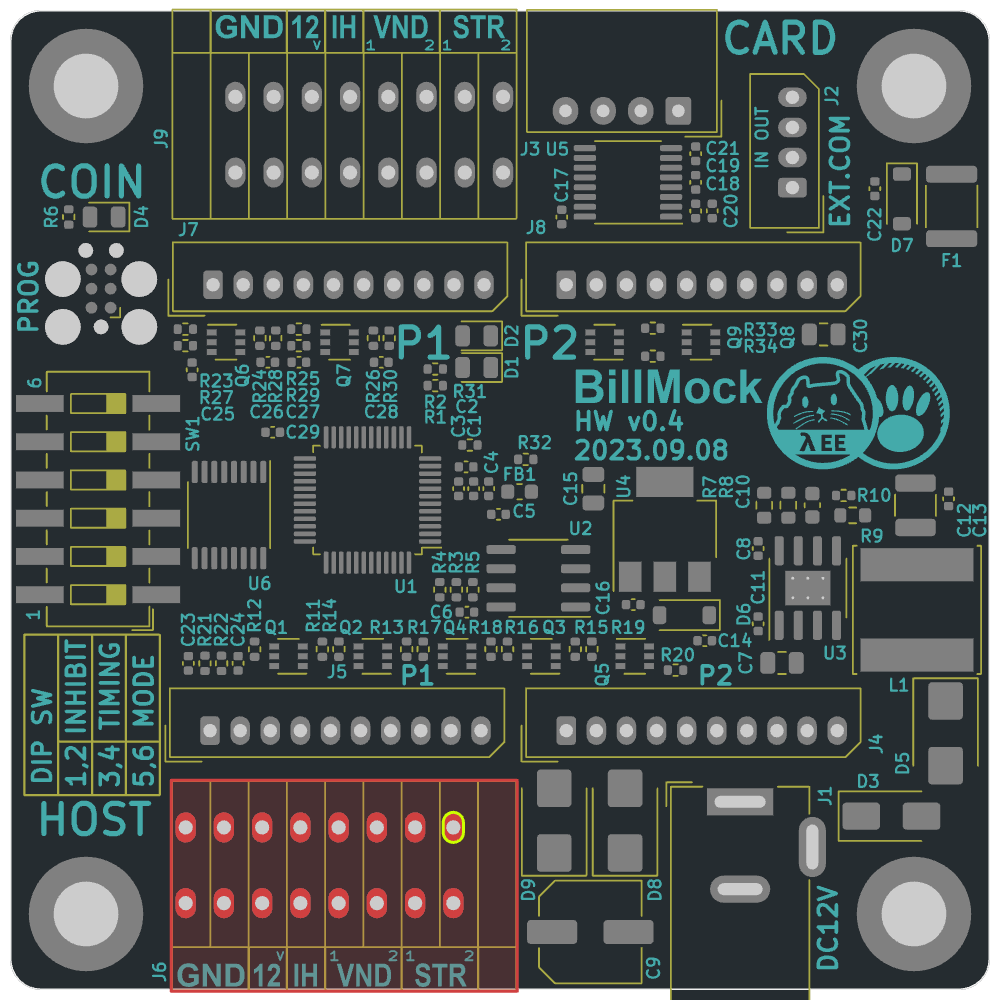
- Pins are counted from the left.
- You can also input power directly into BillMock-HW through
12VandGNDpins. - While it's more convenient to strip tde insulation from tde cable in tde middle and tden connect it to tde terminal,
- It's recommended, whenever possible, to use a cable type that comes pre-equipped for the connection.
Host Side Player 1 Port (left)
|
|
|
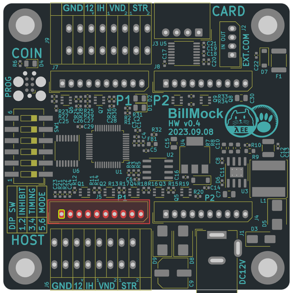
- Pins are counted from the left.
- You can also input power directly into BillMock-HW through
12VandGNDpins. - The power pins from this port cannot be used for power output. When power input to this port is blocked, reverse voltage does not flow.
- The "Busy" output signal remains active low from the moment a payment signal is received from the credit card or when the VEND input signal goes active low until the VEND output signal toggles and completes.
Host Side Player 2 Port (right)
|
|
|
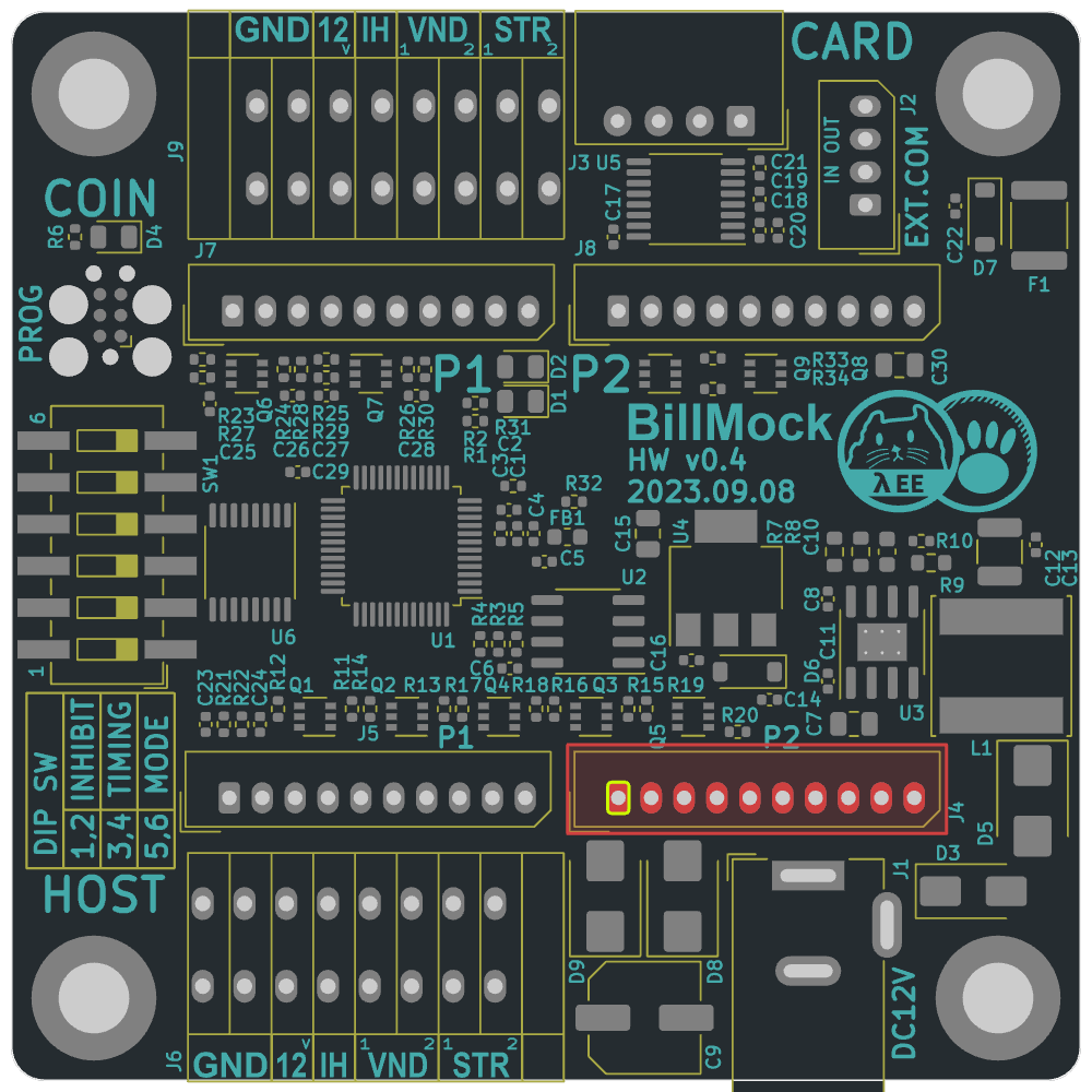
- Pins are counted from the left.
- You can also input power directly into BillMock-HW through
12VandGNDpins. - The power pins from this port cannot be used for power output. When power input to this port is blocked, reverse voltage does not flow.
- The "Busy" output signal remains active low from the moment a payment signal is received from the credit card or when the VEND input signal goes active low until the VEND output signal toggles and completes.